In this update we will go over the basics of setting up a development environment to work with the ESP32. The documentation on the Espressif website is pretty good, so this will be just a short overview and if any issues arise as you’re following these instructions just defer to their info.
The ESP32 is a afforable low-powered Wi-Fi and Bluetooth enabled microcontroller developed by Espressif. It also happens to be what we are using as the backbone for a number of devices in the ZeusNET since it is cheap and easy to integrate. A large number of people interface with this mcu through the Arduino library, which is perfectly fine, but for our project we’ve instead opted to use the library directly from Espressif instead.
The zeusCAM, a wifi connected security camera, is the first device we’ve released firmware for publicly. In it’s current early development phase we are targeting a board called the ESP32-CAM, which is exactly what it sounds like; an ESP32 board with a camera attached. These can be found on Amazon with an OV2640 ribbon attached camera relatively cheap and usually come in packs. In the future we aim to slim down the zeusCAM with custom boards, but that’s a story for another day.
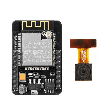
Another thing of note is that some stores sell an accompanying ESP32-CAM-MB, which will be required if you do not have a way to connect to the serial ports on the ESP32. I would reccomend that if you plan on intefacing with more boards in the future, you instead opt to get a USB to Serial breakout board, a breadboard, and some jumper wires. It will require a little more reading and setup, but you’ll be able to interface with any device as long as you know where to connect the wires.
This guide assumes you’re running some sort of Linux; if you’re using something else, refer to the Espressif documentation. Anyway, you’ll need to install a number of dependencies through your distros package manager, on Ubuntu/Debian that looks something like:
sudo apt-get install git wget flex bison gperf python3 python3-venv cmake ninja-build ccache libffi-dev libssl-dev dfu-util libusb-1.0-0
You’ll then need to clone the esp-idf repository locally using git, like so:
git clone --recursive https://github.com/espressif/esp-idf.git
cd into that directory and run the install script, ./install.sh esp32. Then run the export script to setup your environment variables with . ./export.sh. These envrionment variables are temporary and specific to the terminal you have open, the Espressif documentation reccomends using an alias to create a command which will give you back those environment variables easily. This is done by adding the following to something like your ~/.bashrc file.
alias get_idf='. $HOME/platforms/esp/esp-idf/export.sh'
Make sure to change the path to be where you downloaded the library, mine is located in my home directory under a folder named platforms.
Congratulations! You should now have a working ESP-IDF toolset.
So, now let’s build the zeusCAM firmware and flash it onto your ESP32-CAM. You’ll first need to grab a copy of the firmware from our repository.
git clone https://github.com/zeus-technologies/zeusCAM.git
Then cd into that directory, make sure you’re tools are setup in the terminal window (if not run get_idf). To compile we’ll first run idf.py build which should build the project.
Now that the project is built, we need to flash it onto our device, but first we need to connect our device. If you’re using the ESP32-CAM-MB, just plug the board into the headers and connect it to your computer; you can skip the following. If you opted for a generic serial to usb board, you’ll need to wire it in properly. You’ll need to wire the 3v3 pin on the ESP32 to power on your Serial board, GND needs to go to GND. Then we’ll need the TXD to RXD and RXD to TXD. The next “gotcha” is that the ESP32 needs pin 101 to be connected to GND during flashing, so wire that in. If you now connect it to your PC, on Linux you should have a new device in your /dev/ directory, for me it is /dev/ttyUSB0 but it may be something else for you. You can ls the directory while it’s plugged in and again when it isn’t to see what device is getting disconnected.
With that all setup, we just need to run idf.py -p /dev/ttyUSB0 flash which will flash the device. You can now disconnect the wire that goes from pin 101 on the ESP32 to GND and press the tiny reset button on the board. It should then boot up using the newly flashed firmware. To interface with this device now you can open a screen session with screen -p /dev/ttyUSB0 115200 (115200 is the baud rate of the serial connection). You should see a stream of debug information.
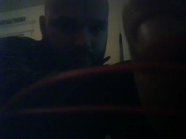
Refer to the zeusCAM repository for a complete list of commands, but you can set the wifi information with set ssid MY_WIFI_SSID_2G and set pass TooManySecrets, replace the ssid and pass with your actual wifi information (it will need to be 2G wifi, since the board does not support 5G). Press the little reset button again and it should be connected to your wifi, if you look at the logs you’ll see what IP address the device was given. If you go to the path /snap at that IP address you should be greeted with a lovely photo from your zeusCAM.
Here’s my ugly mug as seen by the zeusCAM.
And that’s it. The process is still obviously very much in alpha development. A web-based control panel for the zeusNET is being developed which will remove the need to enter any sort of commands; allowing users to just select the firmware from a dropdown and flash directly. But at least now you know how it works under the hood, and you now also have the ability to tweak the code yourself and test it out on the device.
Happy hacking!